Configure Print Parameters
Before configuring print parameters, you need to add a printer first. If you have not added a printer yet, click the add button in the configuration management bar at the bottom of the main window, or add it from the Config menu at the top of the main window.
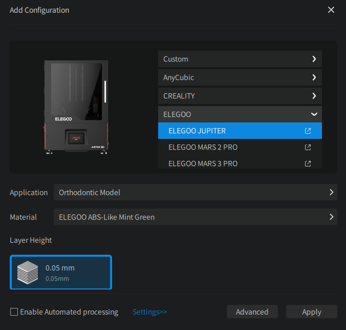
Select the printer brand to expand the available printers, select the machine, application, material, and layer thickness you want to add, and click the Apply button to apply the set configuration. In addition to the machines built into the software, you can also add the custom machine.
After selecting the application, you can check the "Enable automatic processing workflow" option in the lower left corner to set up the automation processing workflow for the application you selected.
You can configure the print parameters for the machine. A machine can have multiple profiles. You can click the Advance Settings button to open the Profile panel and manage your configuration files.
Material
Here you can configure the material's basic information, including the material's color, density, unit price, etc. CHITUBOX will use this information to calculate the material usage and cost.
Not all printers support Resting Time waiting mode. Read the 📃full compatibility list here.
TSMC (Two-Stage Motion Control)
You might have noticed that there are two sets of lifting and retracting parameters in the print settings, this is where you can set up TSMC.
And you might think what TSMC is and why it is needed. Let me explain.
When the build plate starts lifting, the model will be pulled up by the build plate. This is called the "suction effect". The suction effect is more obvious when the contact area with the build plate is large and when the build plate is pulled away quickly. The suction effect can cause the model to deform, and even cause the model to fall off the build plate. So you have to keep it slow at first. But once the model is lifted off the FEP film, the suction effect will disappear. At this time, you can speed up the lifting speed to improve the printing efficiency. The principle acts similarly in the retracting stage.
You can tweak around the parameters below to get familiar with TSMC.
GCode
Don't edit anything here if you don't know what you're doing.
Only .zip and its derived formats (ex. .cws) support Gcode editing.
Slicing
Image Grayscale
Similar to Light PWM, from 0 to 255, instead of controlling the power of the UV light source, Image Grayscale controls the light transmittance of the LCD screen. The higher the value, the higher the light transmittance.
Anti-Aliasing
Grayscale Range
The gray scalerange that can be used for anti-aliasing. The gray scalerange can be adjusted by dragging the slider, clicking on the number above the grays cale bar, or directly entering the number in the input boxes on the left and right.
The default grayscalerange is 0 ~ 255. 0 represents black, and 255 represents white.
Blurred Edges
Blurs the edges of the image to achieve a better surface smoothing effect.
- Blur Pixel Count (px): Available values:
2 ~ 8. Determines the number of pixels that the image edge transitions, the higher the level you choose, the softer the edge will be. Similar to the feather function in Photoshop.
Scale Compensation
Scale compensation of the model in X, Y, and Z directions. The percentage represents the size compared to the original size, the default value is 100%.
When the percentage value is larger, the model body is larger.
When the percentage value is smaller, the model body is smaller.
Tolerance Compensation
Bottom Layers
Inner and outer diameter compensation of bottom printing layers
When a is larger, the inner diameter is shorter, and the model body is larger.
When a is smaller, the inner diameter is longer, and the model body is smaller.
When b is larger, the outer diameter is longer, and the model body is larger.
When b is smaller, the outer diameter is shorter, and the model body is smaller.
Normal Layers
Inner and outer diameter compensation of normal printing layers.
When a is larger, the inner diameter is shorter, and the model body is larger.
When a is smaller, the inner diameter is longer, and the model body is smaller.
When b is larger, the outer diameter is longer, and the model body is larger.
When b is smaller, the outer diameter is shorter, and the model body is smaller.
Mask
Mask is designed for a commonly seen issue that is uneven light strength from points to points on the screen and is mostly caused by improper light sources. The purpose of the mask is to provide a correction layer on the screen by adjusting the transmittance on different areas of the screen respectively, make the uneven light homogeneous.
Mask File : You can select an existing image by clicking Select icon or click create a new one using CHITUBOX's built-in mask generator by clicking the gear icon.
Gray scale unit : click here to learn more about gray scale unit.
Mask Generator
Radial Type
Radial Type generate a ripple-like pattern. The number of circles is set by Number of equal parts. Radius of circles are arithmetic sequence, increases by Equal radius.
The range of Gray Parameter is available from 0 (black) to 255 (white).
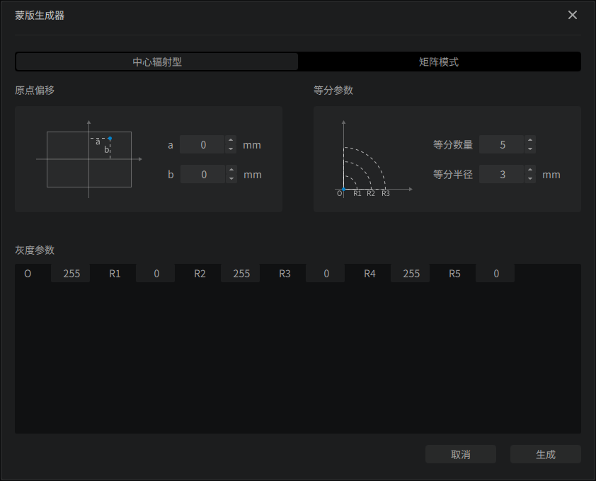
For example, if Number of equal parts is set to 5, Equal radius is set to 3mm, the radius of the ripple will be
here is a comparison for different Equal radius:
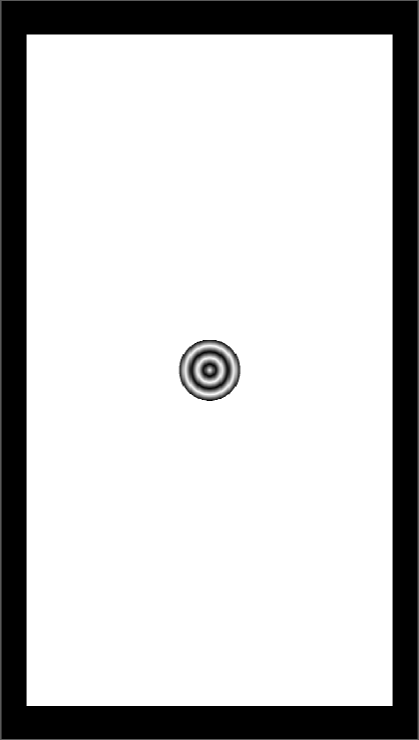 Number of equal parts set to 5, | 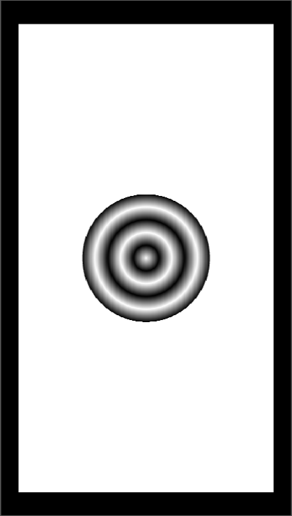 Number of equal parts set to 5, |
|---|
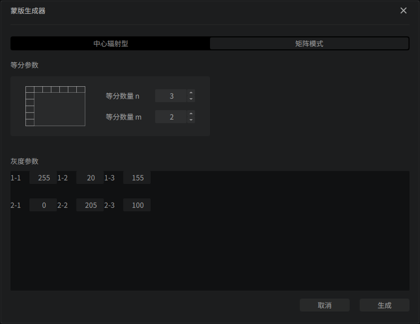
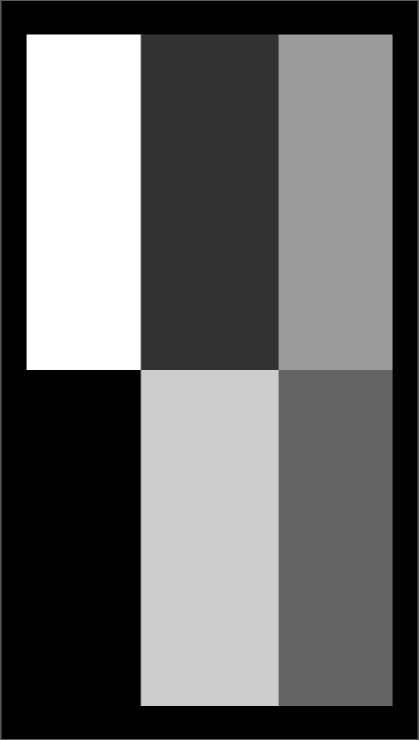
Matrix Type
Matrix Type generate a matrix-like pattern. Rows and columns are set by m and n respectively.
The range of Gray Parameter is available from 0 (black) to 255 (white).
For example, here is a 2 3 matrix with different grayscales.
Gray scale unit (px)
The way Gray scale unit work is to average the grey value of specified number of pixels in X-axis direction, and apply averaged grayscale to pixels in corresponding position of the original image.
Example:
Let's say the size of the build plate is 80mm 120mm, the resolution of the screen is 800px 1200px.
This is the mask picture, also with resolution of 800px 1200px. All squares in the picture have the size of 50px 50px.

If the Gray scale unit was set to 51px, the processed image will be like this:
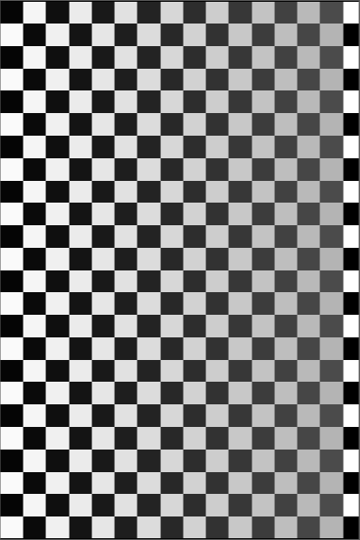
The grayscale of the image goes gray gradually from the left to right, this is because the original image was averaged every 51 pixels in the X-axis direction. Let's consider the first row. The grayscale of the first 51px is averaged by 50 black pixels and 1 white pixel, so it resulted in a width of 51 pixels section that is a little bit lighter than black, even though the change is not visible. The second 51px is composed of 49 white pixels and 2 black pixels, it resulted in a darker average grayscale than white. The third 51px, composed of 48 black pixels and 3 white pixels, and so forth... until there is a remainder left which is composed of 35 white pixels.
, remainder 35
This part will be averaged by 35 pixels themselves, therefore, the grayscale didn't change.
Automatic Processing Flow
Set up an automatic processing workflow for the currently selected application.
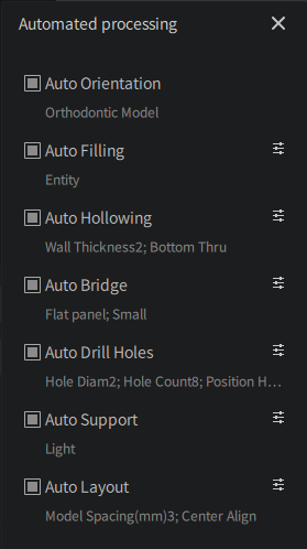
Currently, it is only effective for some applications, including orthodontic models, restorative models, implant surgery guides, occlusal night guards, and temporary crowns.
Click "Settings >>" to open the automatic processing workflow settings window, and then further set up the specific automatic workflow as needed.
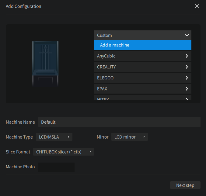
Custom Machine
Expand the custom machine list and click Add a machine. Then you can configure the basic information of the machine, including the machine name, machine resolution, size, etc.
If you have added a custom printer, you can click the icon to enter the machine configuration interface to modify the machine parameters.
Machine Name
The name of the machine. The default is "Default1".
Machine Type
The type of the machine. The available options are: LCD/MSIA, DLP.
Mirror
The exposure image mirror mode.
Slice Format
Set the slice format supported by the printer.
Machine Image
You can customize the display image of the current machine, which is optional. So if you don't upload one, a default image will be shown instead. The supported image formats are: .png, .jpg, and .svg.
Resolution and Size
The resolution and size of the print screen.
Lock Ratio: Locks the ratio of the dimensions and resolution or the X and Y axes.
If the ratio of the resolution and size is not locked (resolution stays unchanged), the smaller the screen size, the larger the actual print will be, and vice versa.
The resolution must matches the actual resolution of the printer, otherwise the printer might report an error.
Build Offset Area
The offset of the build area. By enabling this option, you can adjust the offset to the edge of the printing screen. The offset area will not be printed. If your screen has dead pixels on the edges, you can set the offset to avoid the dead pixels.
Click "Next" to open the configuration panel and manage your profiles.